https://boda.su/en/posts/id2971-home-grounding-why-triangular-loops-beat-single-rods
Home grounding: why triangular loops beat single rods
How a home grounding loop works and why the triangle wins
Home grounding: why triangular loops beat single rods
Learn how a home grounding loop protects against shock, why single rods rarely meet resistance goals, what PUE allows, and triangular layouts deliver results.
2025-12-10T05:54:55+03:00
2025-12-10T05:54:55+03:00
2025-12-10T05:54:55+03:00
Home earthing isn’t a box to tick; it’s what keeps a fault from turning a metal casing into a shock risk. Here’s how a grounding loop does its job, why a single rod seldom delivers, what the rules allow, and why a triangular layout so often becomes the practical choice.Why a grounding system mattersIf a device’s insulation fails, voltage can appear on the case. Touch it, and the human body may become the path for current. With a proper earthing loop, a fault current goes along the path of least resistance—into the ground, not through a person. For the setup to work as intended, ground resistance must be low. In homes, a value no higher than 30 ohms is recommended; if possible, aim for about 8–10 ohms.Why a single rod in the soil isn’t enoughOne vertical electrode rarely provides the required resistance. Dense or dry soil worsens electrical contact. Specialized instruments are used to measure resistance, yet testing isn’t always done. In everyday practice, people sometimes check with an incandescent bulb by connecting it between the phase and the ground loop; if it lights brightly, the contact is treated as acceptable.What the rules sayChapter 1.7 of the PUE sets out grounding requirements. It doesn’t mandate a triangular shape, but it recommends using metal structures buried in the soil. Using metal pipes from water supply, sewer, or gas systems is prohibited because they pose additional risks.Why the triangle often winsElectrodes can be arranged in a straight line or in other patterns. In private construction, though, a triangle tends to prevail for a few straightforward reasons:it’s easier to position on a plot;equal spacing between electrodes is simpler to maintain;the shape is stable and promotes even current dispersion.Typically, the triangle’s side equals the electrode length. Standards call for spacing of roughly 2.2 times the rod length; put them closer, and performance drops.How materials are chosenRebar or angle steel with a diameter of about 16 mm is often used. Angle iron is easier to drive, but rebar and bare steel generally rust quickly. Under GOST, galvanized or copper‑clad rods are recommended. There are ready-made kits on the market—several 1.5‑meter galvanized sections that connect to reach the desired depth and resistance.Soil is the key factor in effectivenessA loop’s performance depends less on rod length than on soil moisture. In wet ground, resistance is lower; in dry conditions, a longer or more branched system is needed. The rods are tied together with a metal strip, forming a single structure that reliably carries fault current and keeps the home’s electrical network safe.The triangular grounding loop became popular not because of a rule, but because it proves practical. It’s straightforward to install, yields predictable results, and helps achieve the target resistance even in difficult soils. With quality materials, the system serves longer and keeps doing its protective job reliably.
home grounding, grounding loop, earthing loop, triangular layout, single ground rod, ground resistance, PUE requirements, copper-clad rods, soil moisture, fault current, electrical safety
2025
articles
How a home grounding loop works and why the triangle wins
Learn how a home grounding loop protects against shock, why single rods rarely meet resistance goals, what PUE allows, and triangular layouts deliver results.
Generated by DALL·E
Home earthing isn’t a box to tick; it’s what keeps a fault from turning a metal casing into a shock risk. Here’s how a grounding loop does its job, why a single rod seldom delivers, what the rules allow, and why a triangular layout so often becomes the practical choice.
Why a grounding system matters
If a device’s insulation fails, voltage can appear on the case. Touch it, and the human body may become the path for current. With a proper earthing loop, a fault current goes along the path of least resistance—into the ground, not through a person. For the setup to work as intended, ground resistance must be low. In homes, a value no higher than 30 ohms is recommended; if possible, aim for about 8–10 ohms.
Why a single rod in the soil isn’t enough
One vertical electrode rarely provides the required resistance. Dense or dry soil worsens electrical contact. Specialized instruments are used to measure resistance, yet testing isn’t always done. In everyday practice, people sometimes check with an incandescent bulb by connecting it between the phase and the ground loop; if it lights brightly, the contact is treated as acceptable.
What the rules say
Chapter 1.7 of the PUE sets out grounding requirements. It doesn’t mandate a triangular shape, but it recommends using metal structures buried in the soil. Using metal pipes from water supply, sewer, or gas systems is prohibited because they pose additional risks.
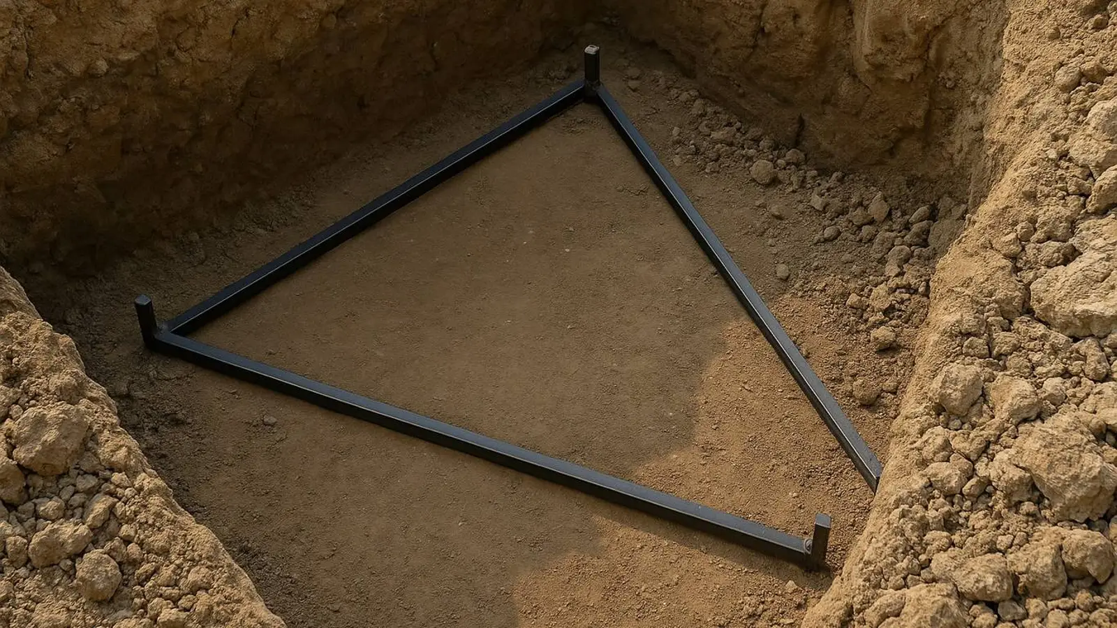
Why the triangle often wins
Electrodes can be arranged in a straight line or in other patterns. In private construction, though, a triangle tends to prevail for a few straightforward reasons:
- it’s easier to position on a plot;
- equal spacing between electrodes is simpler to maintain;
- the shape is stable and promotes even current dispersion.
Typically, the triangle’s side equals the electrode length. Standards call for spacing of roughly 2.2 times the rod length; put them closer, and performance drops.
How materials are chosen
Rebar or angle steel with a diameter of about 16 mm is often used. Angle iron is easier to drive, but rebar and bare steel generally rust quickly. Under GOST, galvanized or copper‑clad rods are recommended. There are ready-made kits on the market—several 1.5‑meter galvanized sections that connect to reach the desired depth and resistance.
Soil is the key factor in effectiveness
A loop’s performance depends less on rod length than on soil moisture. In wet ground, resistance is lower; in dry conditions, a longer or more branched system is needed. The rods are tied together with a metal strip, forming a single structure that reliably carries fault current and keeps the home’s electrical network safe.
The triangular grounding loop became popular not because of a rule, but because it proves practical. It’s straightforward to install, yields predictable results, and helps achieve the target resistance even in difficult soils. With quality materials, the system serves longer and keeps doing its protective job reliably.